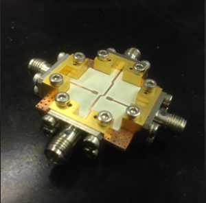
Novel signal cross coupling method

Signal couplers allow signals from two transmission lines to be combined and/or split, and can be used in a variety of applications including power distribution networks, sensor arrays, and astronomical instrumentation. Conventional couplers have both transmission lines, which carry the signal, running in parallel to each other, which makes them unsuitable for circuits that require signal path crossing or bypassing, particularly in applications in a linear array. Traditionally this is overcome by using cross-guide coupler, additional cabling or series of optical free-space beam splitters. These solutions are often bulky and space-consuming. Furthermore, it is difficult to integrate them with standard planar circuits.
Oxford University academics have recently developed a signal coupler with crossed transmission lines in planar circuit form, which results in a much more compact device that is much easier to manufacture. The coupler can easily be integrated directly into a wider range of circuitry on printed circuit boards. This could have a major impact on how one can design and simplify complicated circuitries that require multiple signal couplers, reducing the size of components and improving their performance.
Signal couplers are very common circuit components in many applications, ranging from radio frequencies (kHz) to optical frequencies (THz). They are widely used for power distribution networks, heterodyne mixing applications, large sensor arrays and phase delay networks. Their primary function is to couple a defined amount of signal from one transmission path to the other, and hence can be used to combine or split signals.
Traditionally, a planar circuit-based signal coupler has both of its transmission paths aligned in parallel to each other. Whilst this is suitable for simple circuitry, it can be difficult to implement for large complex systems, since the flexibility in routing the transmission paths is limited by the coupler.
This is particularly important for large array networks, where it is preferable to have the ability to cross or bypass the transmission line using additional cablings, crossing waveguide couplers or optical free-space beam splitters. These methods are incompatible with standard radio to terahertz circuitries.
Powerful advances
Academics at the University of Oxford have developed a signal coupler that can be easily integrated into wider circuitry in planar circuits (e.g. printed circuit boards (PCBs)). They are easy to fabricate with standard PCB technology and are compact, broadband and easy to scale for applications in different frequency domains.
The inter-arm power coupling can be configured to be directional or non-directional. More importantly, the level of power coupling can be easily and reliably controlled and adjusted with simple alterations to the circuit, which makes it easier to design for large complex networks that require a large number of couplers with different power coupling levels.
More than a couple of benefits
This new signal coupler has multiple other benefits, including:
- Reduced losses compared to traditional signal couplers
- Can be scaled to work at almost any frequency, from kHz to THz
- Easy to mass produce
- Around 10x smaller than the traditional cross-guide couplers
- Coupling strength can be adjusted easily
- Coupling direction can be designed according to specific applications by simply changing features in the planar circuit design
This could have a major impact on the design of complicated circuitries that require multiple signal couplers, reducing the size of components and improving their performance.
Technology applications
The Oxford-developed signal coupler can replace the traditional, bulky cross-waveguide coupler, as well as the freestanding dielectric beam splitter in heterodyne astronomy receivers, and has applications within satellites, telecommunications and radar, and large power distribution networks such as multiple-path phase array networks.
The technology is subject to a UK patent application and is available for license. If you would like to hear more about the technology, please contact Oxford University Innovation.
about this technology

